Arduino RFID Door Strike
I rediscovered a shelved project over Christmas break, something I had never gotten around to doing. It’s always nice to find an excuse to break out the soldering iron.
The goal was to use an Arduino and an RFID reader to operate an electric door strike, granting or denying access to some door.
Arduinos are micro-controller boards that ease some of the complexity of developing electronics projects. They are great fun to play with and the possibilities they present are virtually endless. If you have never played with an Arduino, check out this series of tutorials by Jeremy Blum. These are very helpful videos, not only for getting up to speed with Arduinos, but also for learning about electrical engineering and circuits. I found these videos a few years back when I first bought the Arduino. I’m not an electrical engineer, so these videos helped me a lot.
I’ll walk through what I did for the RFID door strike project and explain what I can along the way. Perhaps it will be of help to someone attempting a similar project.
Components Used
- Arduino Uno
- SDC 25-4U Electric Door Strike
- ID-20 RFID Reader
- RFID Breakout Board
- RFID Card
- RGB LED
- Capacitors
- 1 x 10 uF
- 1 x 100 uF
- Resistors
- 3 x 100 ohms
- x 150 ohms
- 1 x 1K ohms
- TIP3055 Transistor
- 7805 5VDC Voltage Regulator
- Coaxial Power Jack (Size N)
- 12VDC power supply
- Project box or enclosure for main components
- Project box or enclosure for RFID reader module
- Ethernet cable, RJ-45 jacks or couplers
- Wire, 22 AWG works well
- A breadboard or two and some perfboard
Your components list may differ, depending on what your goals are or simply what you have available. You don’t need to use an Arduino Uno, or an Arduino at all, and other design decisions will be made per designer preference or other constraints.
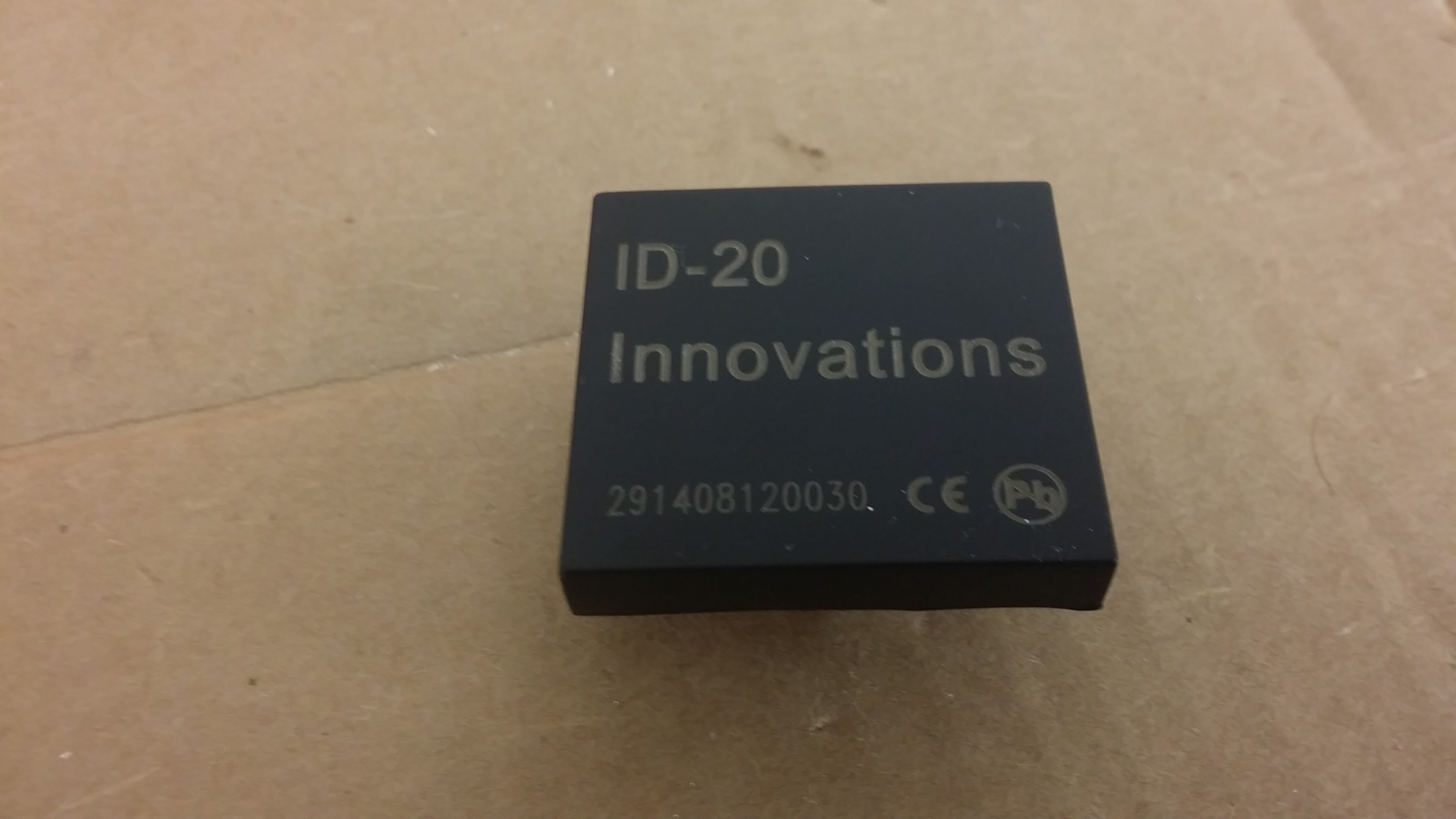
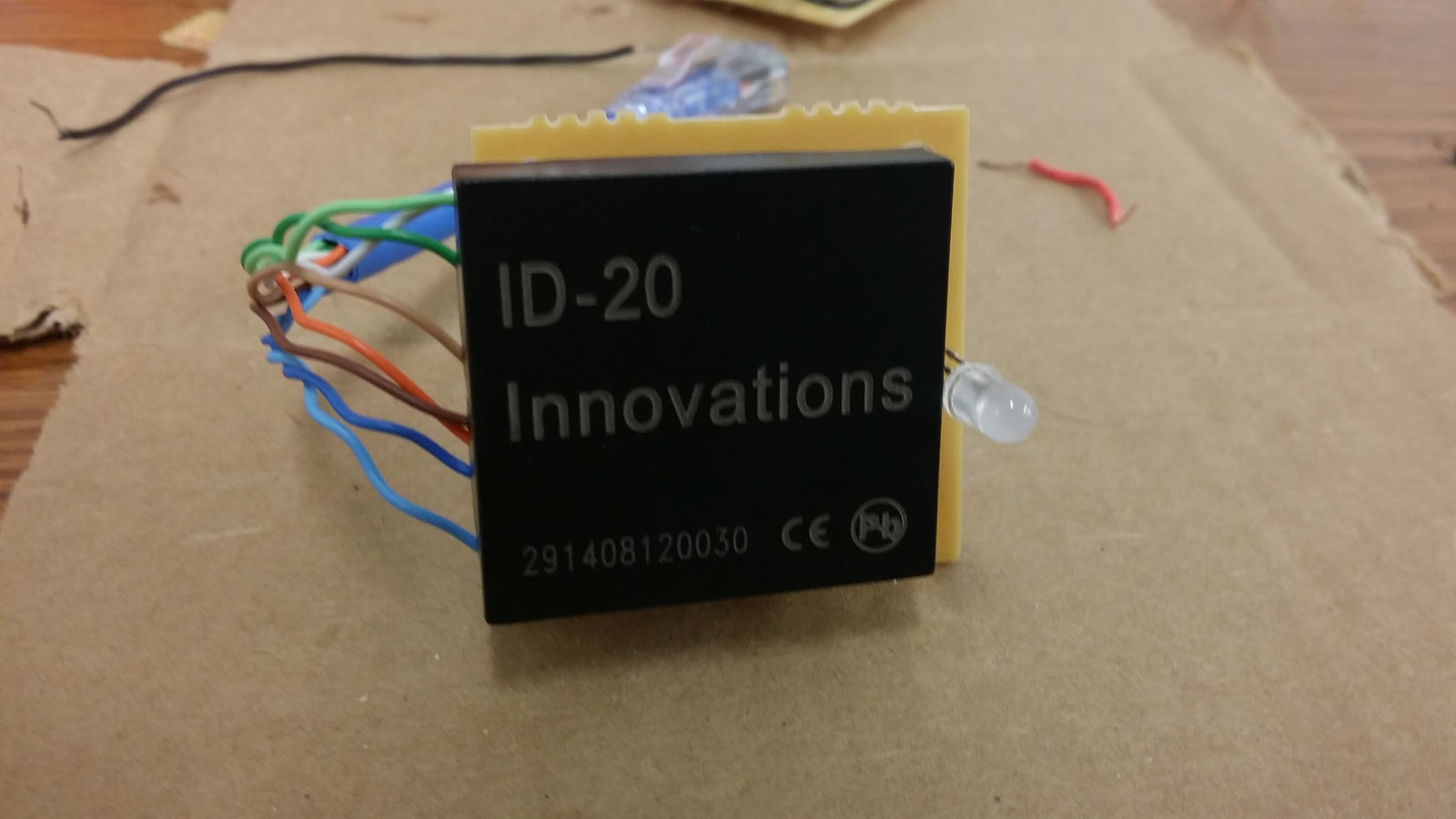
The ID-20
First step is to make sure the RFID reader is functioning and that the Arduino can communicate with it. I highly recommend using the RFID breakout board as it makes prototyping with the reader immensely easier. Using some header pins to attach to the breakout board allows you to pop the ID-20 into and out of breadboards with ease.
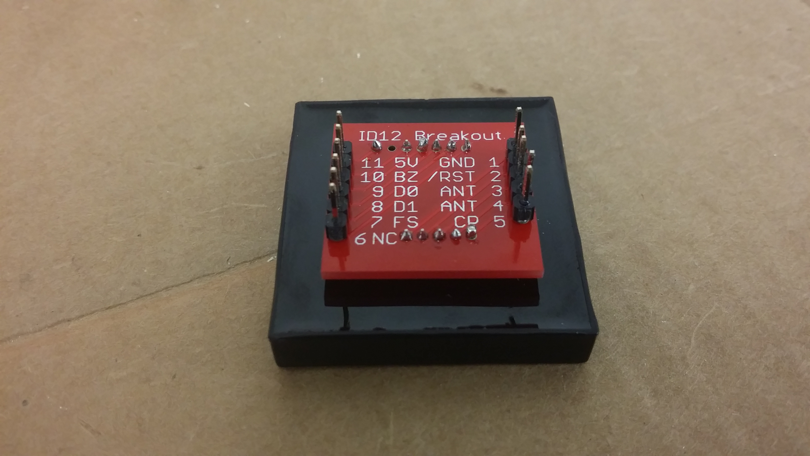
The version of the breakout board I used says “ID12” on it, but it still works with the ID-20. The pins on the bottom of the ID-20 are arranged in such a way that it is impossible to put the breakout board on incorrectly, but it is always a good idea to double check the pinouts and verify everything is correct. Also, it helps to solder the header pins into place before soldering the board to the ID-20 itself.
The datasheet for the ID-20 can be found here.
It’s a good idea to read section 6, “Pin Description & Output Data Formats” in the datasheet, but I’ll highlight some points.
- Pin 1 is ground.
- Pin 2 is strapped to Pin 11.
- Pin 7 is used to specify what data format the ID-20 sends back to the controller.
- The ID-20 can transmit data back in ASCII, magnetic emulation, or Wiegan26.
- ASCII is simple and easy, so that’s what I went with.
- Strap Pin 7 to ground for ASCII.
- Pin 9 is used for data output when the ASCII format is selected.
- Pin 10 provides LED/Beeper functionality for when a card is read.
- Pin 11 is DC power.
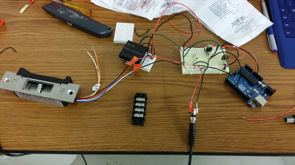
You can setup a simple test circuit with the ID-20 and Arduino to test the reader out.
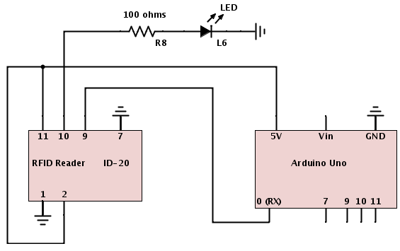
You can use whatever resistor value for (R8) you need for the LED (L6) you are using. The power for the reader is supplied from the Arduino. Note that we connect the LED to pin 10 on the ID-20. When any card is read by the reader, the LED will be lit momentarily.
We can use an Arduino program (called a sketch) to read data that the RFID reader sends back when it reads a card.
/*
* Code adapated from: http://playground.arduino.cc/Code/ID12
*  - Based on code by BARRAGAN <http://people.interaction-ivrea.it/h.barragan>
*  - and code from HC Gilje - http://hcgilje.wordpress.com/resources/rfid_id12_tagreader/
*  - Modified for Arudino by djmatic
*  - Modified for ID-12 and checksum by Martijn The - http://www.martijnthe.nl/
*/

// Code being read in
byte code[6];

void setup()
{
    // connect to the serial port
    Serial.begin(9600);
}

void loop()
{
    byte i = 0;
    byte val = 0;
    byte checksum = 0;
    byte bytesread = 0;
    byte tempbyte = 0;

    if (Serial.available() > 0)
    {
        // check for header
        if ((val = Serial.read()) == 2)
        {
            bytesread = 0;

            // read 10 digit code + 2 digit checksum
            while (bytesread < 12)
            {
                if (Serial.available() > 0)
                {
                    val = Serial.read();

                    // if header or stop bytes before the 10 digit reading
                    if ((val == 0x0D) || (val == 0x0A) || (val == 0x03) || (val == 0x02))
                    {
                        break; // stop reading
                    }

                    // Do Ascii/Hex conversion:
                    if ((val >= '0') && (val <= '9'))
                    {
                        val = val - '0';
                    }
                    else if ((val >= 'A') && (val <= 'F'))
                    {
                        val = 10 + val - 'A';
                    }

                    // Every two hex-digits, add byte to code:
                    if (bytesread & 1 == 1)
                    {
                        // make some space for this hex-digit by
                        // shifting the previous hex-digit with 4 bits to the left:
                        code[bytesread >> 1] = (val | (tempbyte << 4));

                        // If we're at the checksum byte,
                        if (bytesread >> 1 != 5)
                        {
                            // Calculate the checksum... (XOR)
                            checksum ^= code[bytesread >> 1];
                        }
                    }
                    else
                    {
                        // Store the first hex digit first...
                        tempbyte = val;
                    }

                    // ready to read next digit
                    bytesread++;
                }
            }

            // Output to Serial:

            // if 12 digit read is complete
            if (bytesread == 12)
            {
                Serial.print("5-byte code: ");
                for (i = 0; i < 5; i++)
                {
                    if (code[i] < 16)
                        Serial.print("0");

                    Serial.print(code[i], HEX);
                    Serial.print(" ");
                }
                Serial.println();

                Serial.print("Checksum: ");
                Serial.print(code[5], HEX);
                Serial.println(code[5] == checksum ? " -- passed." : " -- error.");
                Serial.println();
            }

            bytesread = 0;
        }
    }
}
This code is taken directly from the Arduino Playground site. I am a huge fan of not re-inventing the wheel if you don’t have to. It is a little more complex than most sample code for the ID-20 as it converts the ASCII characters into their HEX values and performs the checksum calculation. When in ASCII mode, the ID-20 will send back a string of ASCII characters. There are 12 characters we care about. 10 are the ID of the card and 2 are the checksum digits for error checking. Check the data sheet on page 4 for details about the data format.
This sketch will output the card’s ID code to the serial console in the Arduino IDE. Save the ID codes for cards you want to grant access to the door.
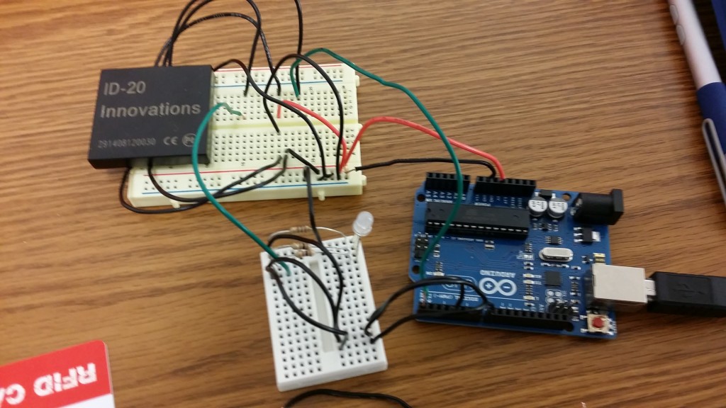
With the test circuit setup and the ID-20 Test sketch loaded on the Arduino, you can test out the RFID reader.
A few notes:
- If an error occurs while uploading a sketch from the Arduino IDE to the Arduino itself, try disconnecting Pin 0 (RX) on the Arduino. After uploading the sketch, you can reconnect the pin.
- The ID-20 will read a card once while it is in range, and not read the card again. You will have to pull the card out of range and re-scan the card. This is by design.
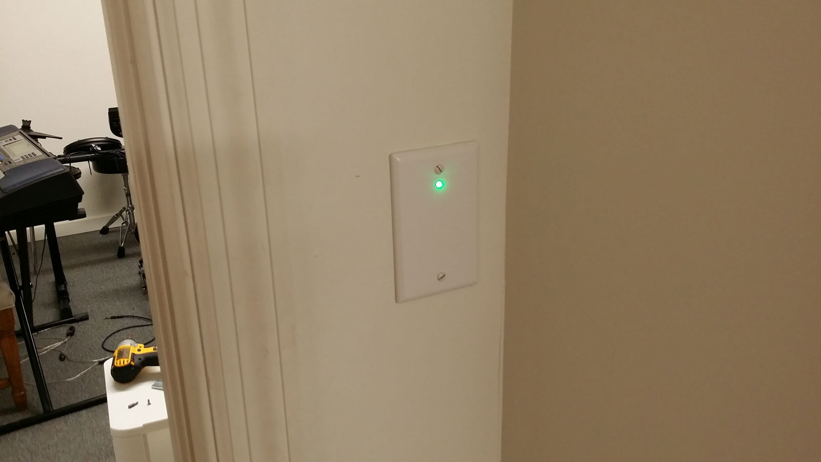
In the final project, I did not use pin 10 (the LED/beeper pin) on the ID-20. Instead, I just controlled an LED to light up green when a card is granted access and red when a card is denied access. You can easily do both (have two LEDs) or use a single LED for access indicator and wire a buzzer/beeper up to pin 10 on the ID-20. Have it your way!
A note on card access: you will want to be able to grant access to certain RFID cards as mentioned. The easiest way is to hard-code IDs into your program (as I did in the final sketch, shown later on). You can make more sophisticated systems if you so desire, such as having “ADD” / “DELETE” cards. Or add an Ethernet/Wifi interface and communicate with a database of validated ID numbers!
The Door Strike
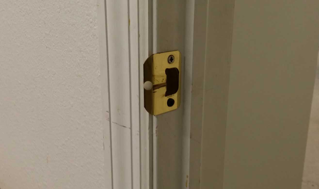
The electric door strike is what controls access to the chosen door. The electric strike operates similarly to a regular, fixed door strike. When locked, the latchbar of the strike is in a fixed position, forcing the door knob to be turned before the door can be opened. The latchbar is ramped, allowing the locking latch in the door to close normally (think when you just push a door closed without turning the knob). What makes an electric strike different is its ability to unlock the latchbar from its fixed position into a movable one. When the strike is unlocked, the door can be pushed open without turning the door knob. Note that the door knob can still operate as normal - if the door knob itself is unlocked, the door can open and close normally no matter what the state of the electric strike.
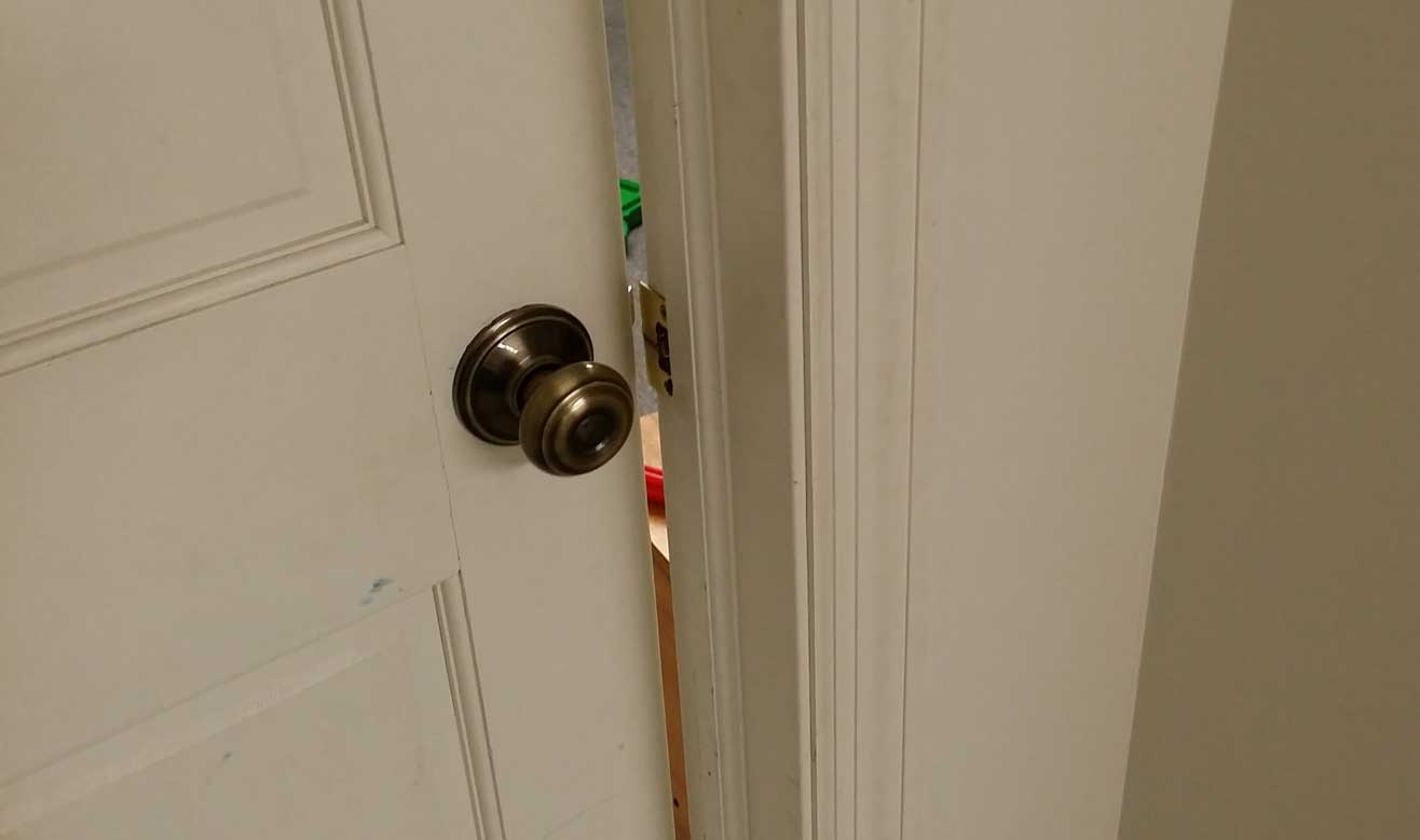
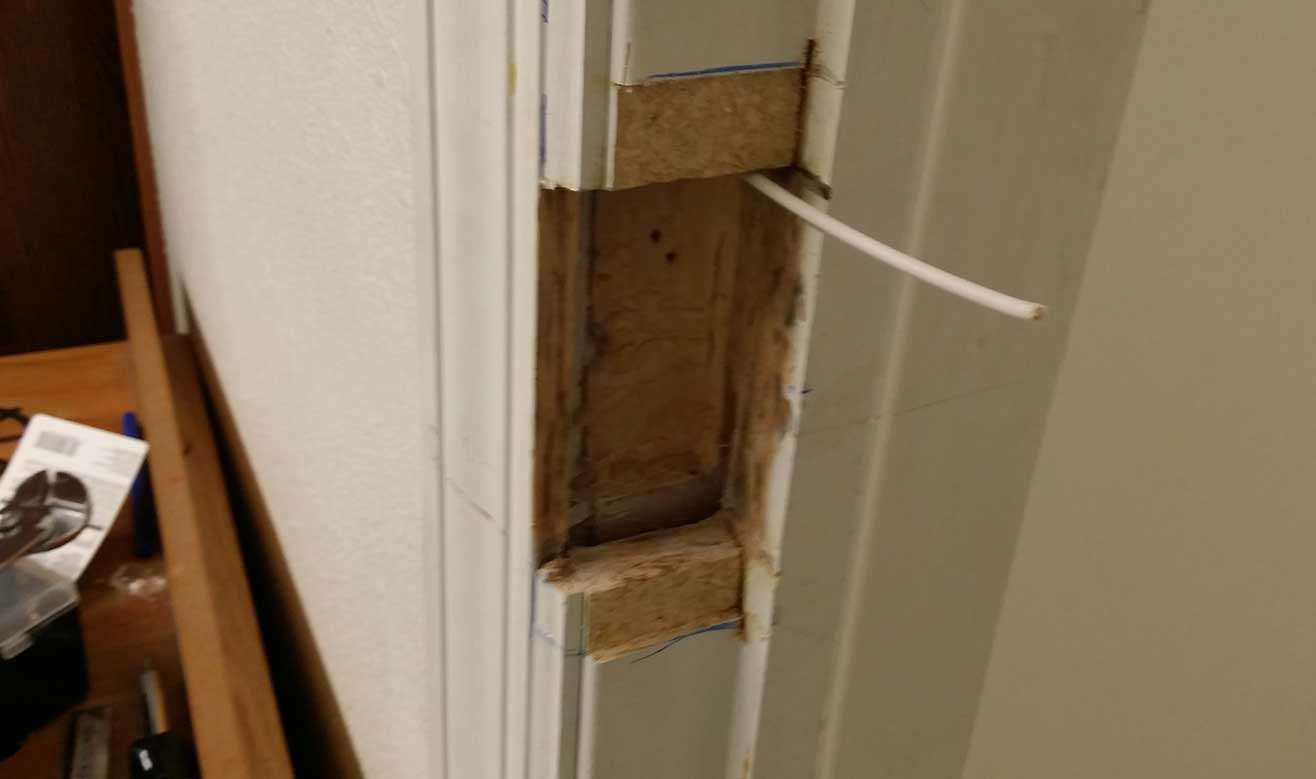
This was a quick time frame project, just a couple days, so I installed the strike into a test door of no importance. A little hacking of the door frame was required to fit the strike, as this was just a simple wooden frame.
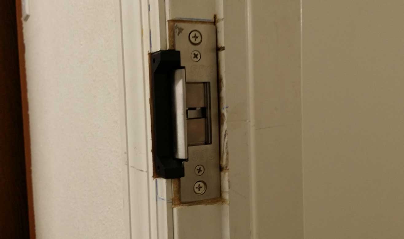
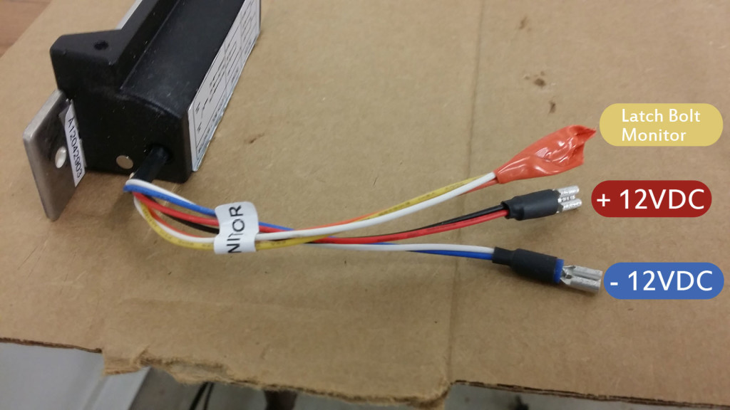
I used the SDC 25-4U Electric Door Strike.
It allows for both “fail safe” and “fail secure” operation:
- Fail Safe: strike is unlocked when there is no power provided to the strike.
- Fail Secure: strike is locked when there is no power provided to the strike.
It allows for operation on either 200mA @ 12VDC or 100mA @ 24VDC. It also provides a latch bolt monitor circuit that will allow you to monitor if the door is open or closed.

I decided to go with the fail-secure configuration. I also decided not to use the latch bolt monitor.
Controlling the Strike
To step back for a second: we now have an RFID reader and a controller that can identify whether a certain RFID card is granted access when it is read. We also have a door strike for the door. Now, the two need to be linked together.
I used the fail-secure configuration for the door strike, so it will always be locked when no power is applied to it. To unlock the strike, power is applied. We want the Arduino to control this flow of power. To do this:
- Create a circuit that is disconnected when the door should be locked.
- Complete the circuit for a period of time (say, 5 seconds) when a card is granted access to the door.
- Break the circuit to re-lock the door.
Since the Arduino operates with 5V and the door strike with 12V, we will need to use a transistor. The transistor essentially acts as a switch, controlling the circuit just described.
When a 5V control signal is sent to the base of the transistor, the circuit for the electric strike will be completed and the door unlocked. This control signal is provided from one of the output pins on the Arduino. When a card is granted access, voltage is applied to that output pin for a set period of time.
There is a great write-up on transistors here by Dan Morris that was of great help. Check it out!
Power
For convenience, I wanted to power both the Arduino and door strike from the same power supply. I had a 110VAC to 12VDC power converter (“wall wart”, “power brick”, or whatever you call it) laying around to use. This is perfect for the door strike, but since the Arduino operates with 5V, a voltage regulator is needed to provide the Arduino with proper voltage.

The capacitors provide stability from fluctuations in the supplied voltage from the power source (its a cheap AC-DC converter). At least that’s my understanding. To be honest, I’m not sure of the “proper” values for the two capacitors, they don’t have to be exactly what I specified in the schematic. In my implementation, I used a 4.7 uF capacitor between the 5V output and ground because I had one on hand.
It should be noted that all components need to be on a common ground, so make sure that all grounds (including the ground pin on the Arduino) are connected to the ground coming from the power supply.
The Final Circuit
With everything tested, the final circuit is complete.
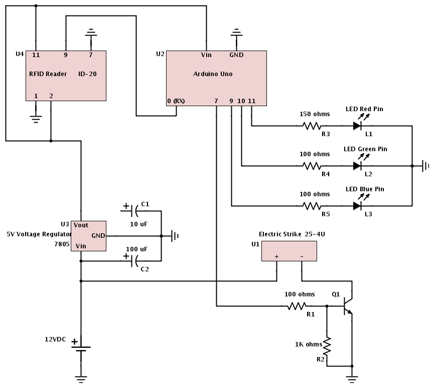
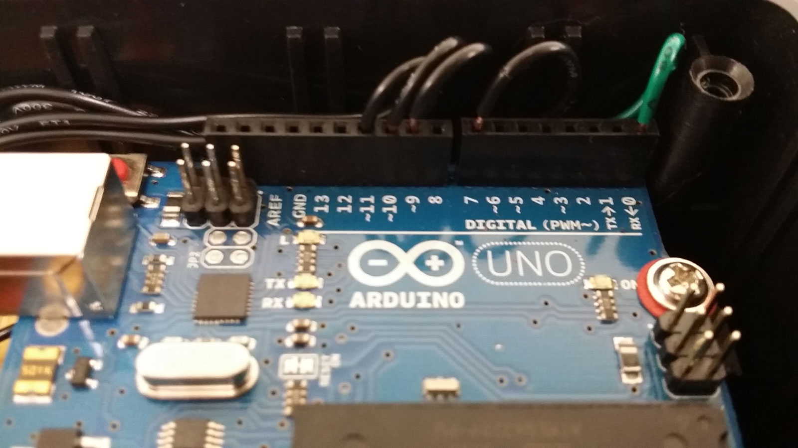
For the Arduino:
- Pin 0 (RX) is for receiving data from the RFID reader.
- Pin 7 is the control signal for opening/closing the door strike.
- Pin 9, 10, and 11 are for the blue, green, and red pins of the access indicator LED.
Everything is powered from the single 12V power source.
The Final Sketch
Here is the final sketch for the Arduino. As I noted previously, I did not write this entire program. I adapted some code to fit my needs.
The “allowedCard1” variable holds the code for the card I want to grant access for. In this case, it’s just all zeros. You would want to put the correct values into this array for the card you want to grant access.
/*
* Arduino RFID Door Strike Project
*  - Victor Bushong
*
* Code adapated from: http://playground.arduino.cc/Code/ID12
*  - Based on code by BARRAGAN <http://people.interaction-ivrea.it/h.barragan>
*  - and code from HC Gilje - http://hcgilje.wordpress.com/resources/rfid_id12_tagreader/
*  - Modified for Arudino by djmatic
*  - Modified for ID-12 and checksum by Martijn The - http://www.martijnthe.nl/
*/

// Pin variables
int strikePin = 7;
int redPin = 9;
int greenPin = 10;
int bluePin = 11;

// Code being read in
byte code[6];

// ID of the card to grant access to. In HEX format, so prefix with 0x
byte allowedCard1[5] = { 0x00, 0x00, 0x00, 0x00, 0x00 };

void setup()
{
    // connect to the serial port
    Serial.begin(9600);

    // Setup pins
    pinMode(strikePin, OUTPUT);
    pinMode(greenPin, OUTPUT);
    pinMode(redPin, OUTPUT);
    pinMode(bluePin, OUTPUT);
}

void loop()
{
    byte i = 0;
    byte val = 0;
    byte checksum = 0;
    byte bytesread = 0;
    byte tempbyte = 0;

    if (Serial.available() > 0)
    {
        // check for header
        if ((val = Serial.read()) == 2)
        {
            bytesread = 0;

            // read 10 digit code + 2 digit checksum
            while (bytesread < 12)
            {
                if (Serial.available() > 0)
                {
                    val = Serial.read();

                    // if header or stop bytes before the 10 digit reading
                    if ((val == 0x0D) || (val == 0x0A) || (val == 0x03) || (val == 0x02))
                    {
                        break; // stop reading
                    }

                    // Do Ascii/Hex conversion:
                    if ((val >= '0') && (val <= '9'))
                    {
                        val = val - '0';
                    }
                    else if ((val >= 'A') && (val <= 'F'))
                    {
                        val = 10 + val - 'A';
                    }

                    // Every two hex-digits, add byte to code:
                    if (bytesread & 1 == 1)
                    {
                        // make some space for this hex-digit by
                        // shifting the previous hex-digit with 4 bits to the left:
                        code[bytesread >> 1] = (val | (tempbyte << 4));

                        // If we're at the checksum byte,
                        if (bytesread >> 1 != 5)
                        {
                            // Calculate the checksum... (XOR)
                            checksum ^= code[bytesread >> 1];
                        }
                    }
                    else
                    {
                        // Store the first hex digit first...
                        tempbyte = val;
                    }

                    // ready to read next digit
                    bytesread++;
                }
            }

            // Output to Serial:

            // if 12 digit read is complete
            if (bytesread == 12)
            {
                Serial.print("5-byte code: ");
                for (i = 0; i < 5; i++)
                {
                    if (code[i] < 16)
                        Serial.print("0");

                    Serial.print(code[i], HEX);
                    Serial.print(" ");
                }
                Serial.println();

                Serial.print("Checksum: ");
                Serial.print(code[5], HEX);
                Serial.println(code[5] == checksum ? " -- passed." : " -- error.");
                Serial.println();

                // Don't validate card if checksum failed
                if (code[5] != checksum)
                    return;

                // Check if card has access
                validateCard();
            }

            bytesread = 0;
        }
    }
}

/**
* Determines if a card has access and acts accordingly.
*/
void validateCard()
{
    // Match each digit of the ID
    for (int i = 0; i < 5; i++)
    {
        // If mis-match detected, the card is invalid
        if (code[i] != allowedCard1[i])
        {
            denyAccess();
            return;
        }
    }

    // If you make it this far, card is good
    grantAccess();
}

/**
* Unlocks the door for a valid card.
*/
void grantAccess()
{
    Serial.println("Valid Card -- Access Granted");

    digitalWrite(strikePin, HIGH);    // Unlock the strike
    digitalWrite(greenPin, HIGH);    // Light Green LED
    delay(5000);                      // Wait for 5 seconds
    digitalWrite(strikePin, LOW);    // Lock the strike
    digitalWrite(greenPin, LOW);    // Shut off LED
}

/**
* Denies access to a card.
*/
void denyAccess()
{
    Serial.println("Invalid Card -- Access Denied");

    digitalWrite(redPin, HIGH);    // Light Red LED
    delay(5000);                  // Wait for 5 seconds
    digitalWrite(redPin, LOW);    // Shut off LED
}
Building the Project
At this point everything worked, but things needed shrunk down into a nice, neat package for final installation.
My approach was to break the project into three main components:
- Main control box
- Connected to power supply
- Holds the Arduino
- Holds voltage regulator circuit
- Holds transistor circuit for controller the strike
- Hidden somewhere
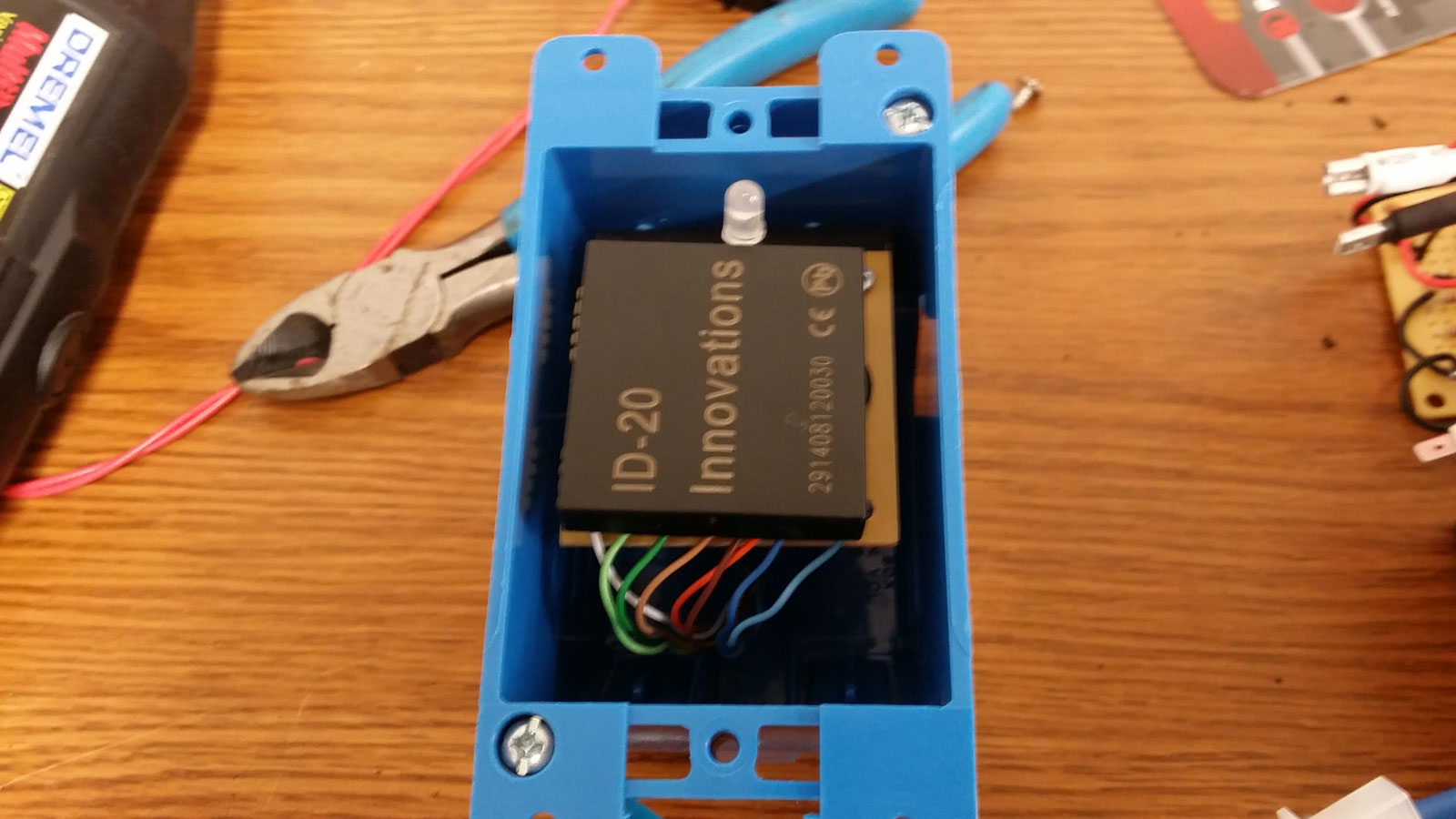
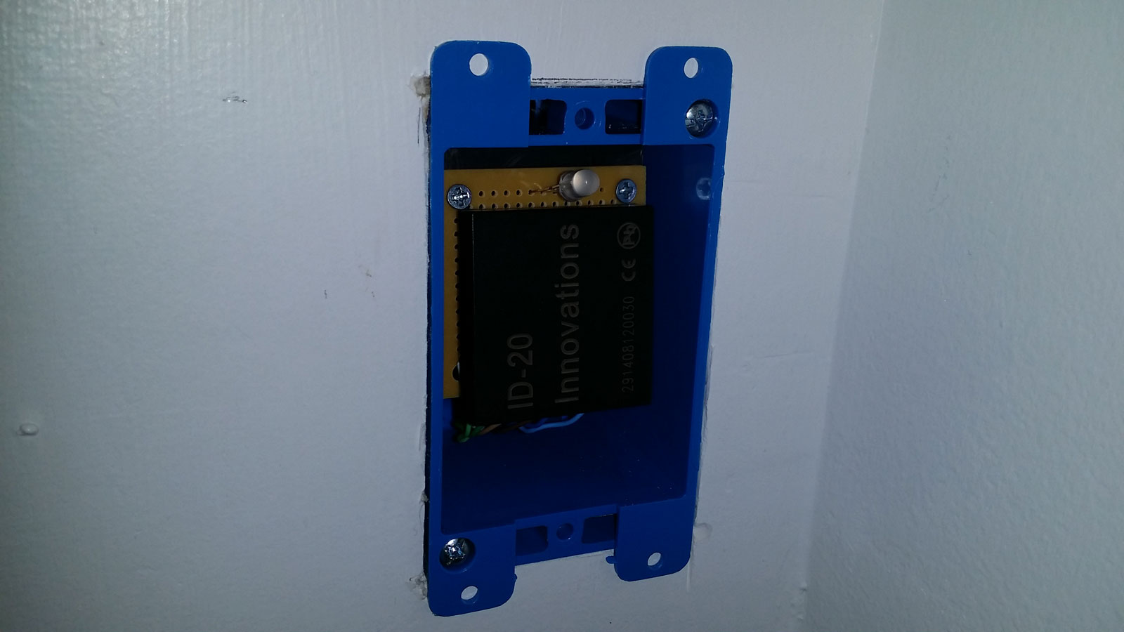
- RFID reader module
- Holds the ID-20 RFID reader
- Holds the access indicator LED
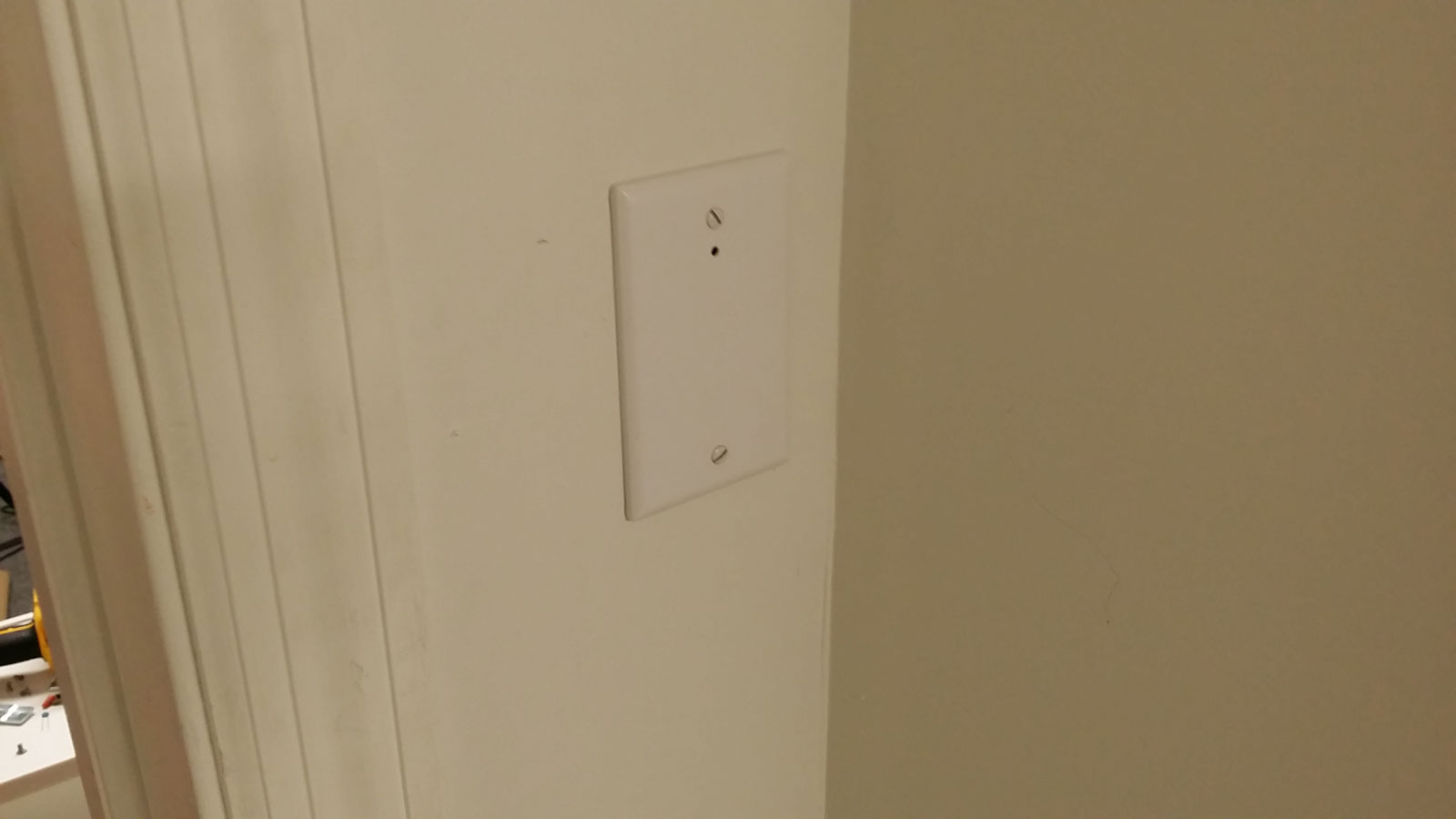
- Mounted in wall outside door
- Door strike
- Mounted in the door frame
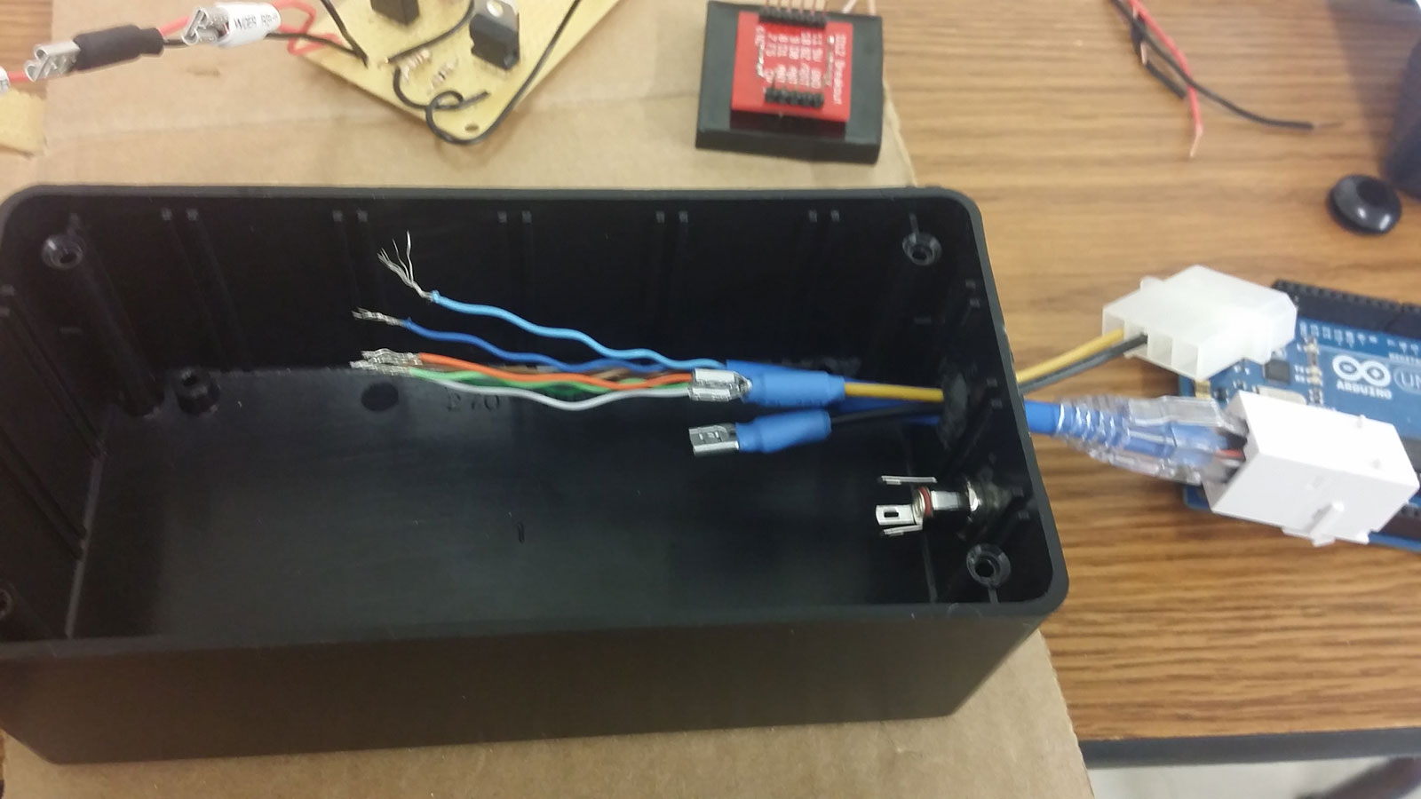
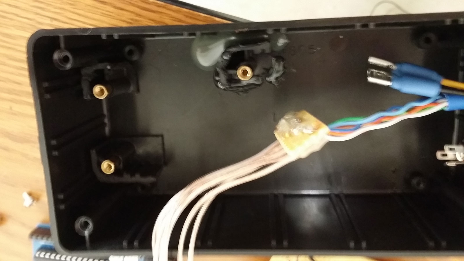
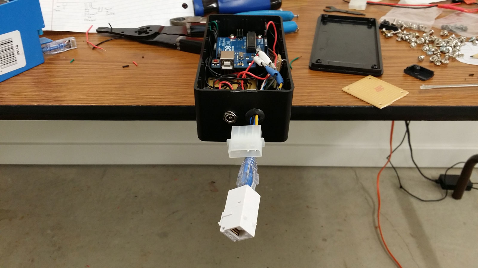
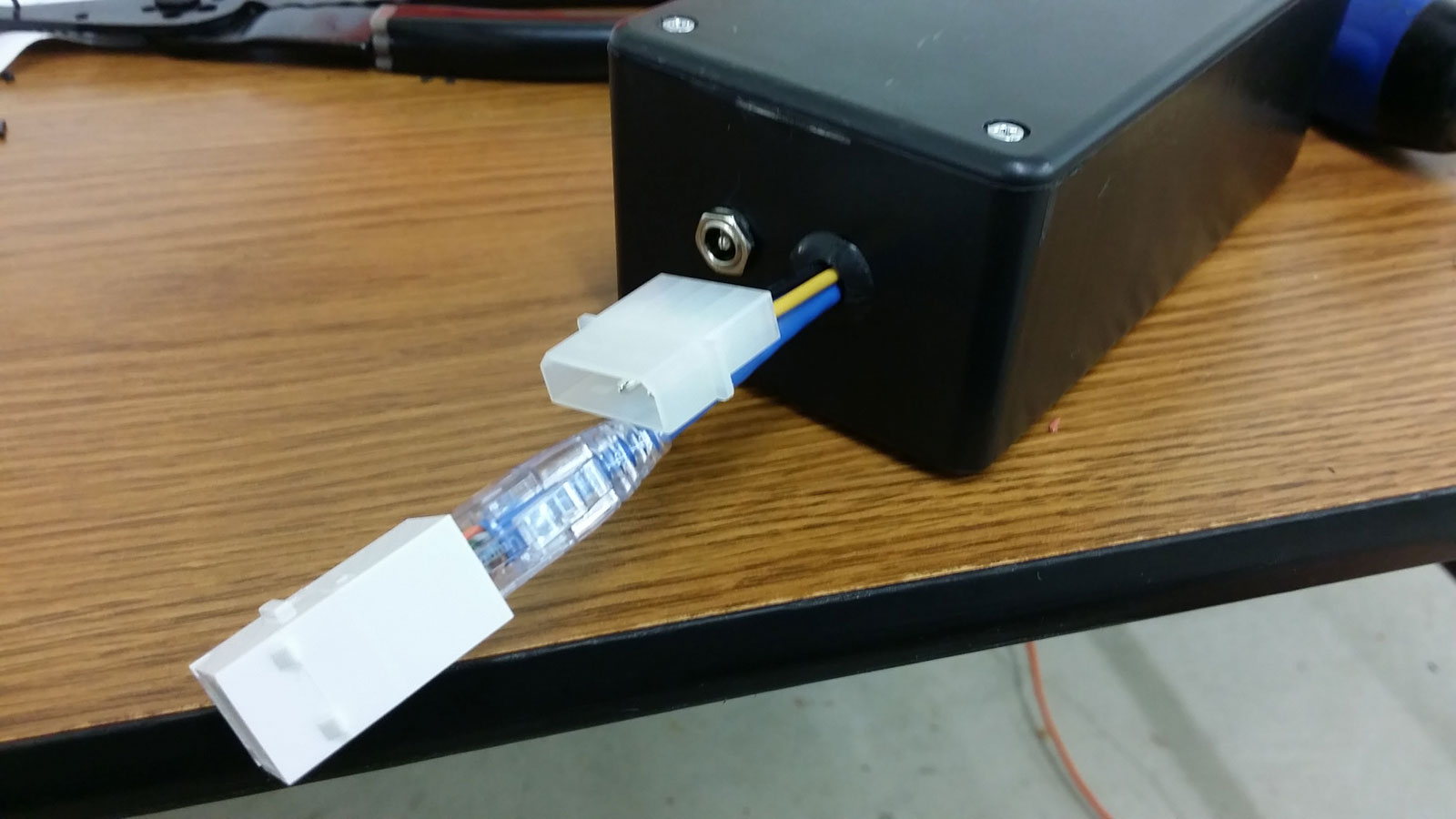
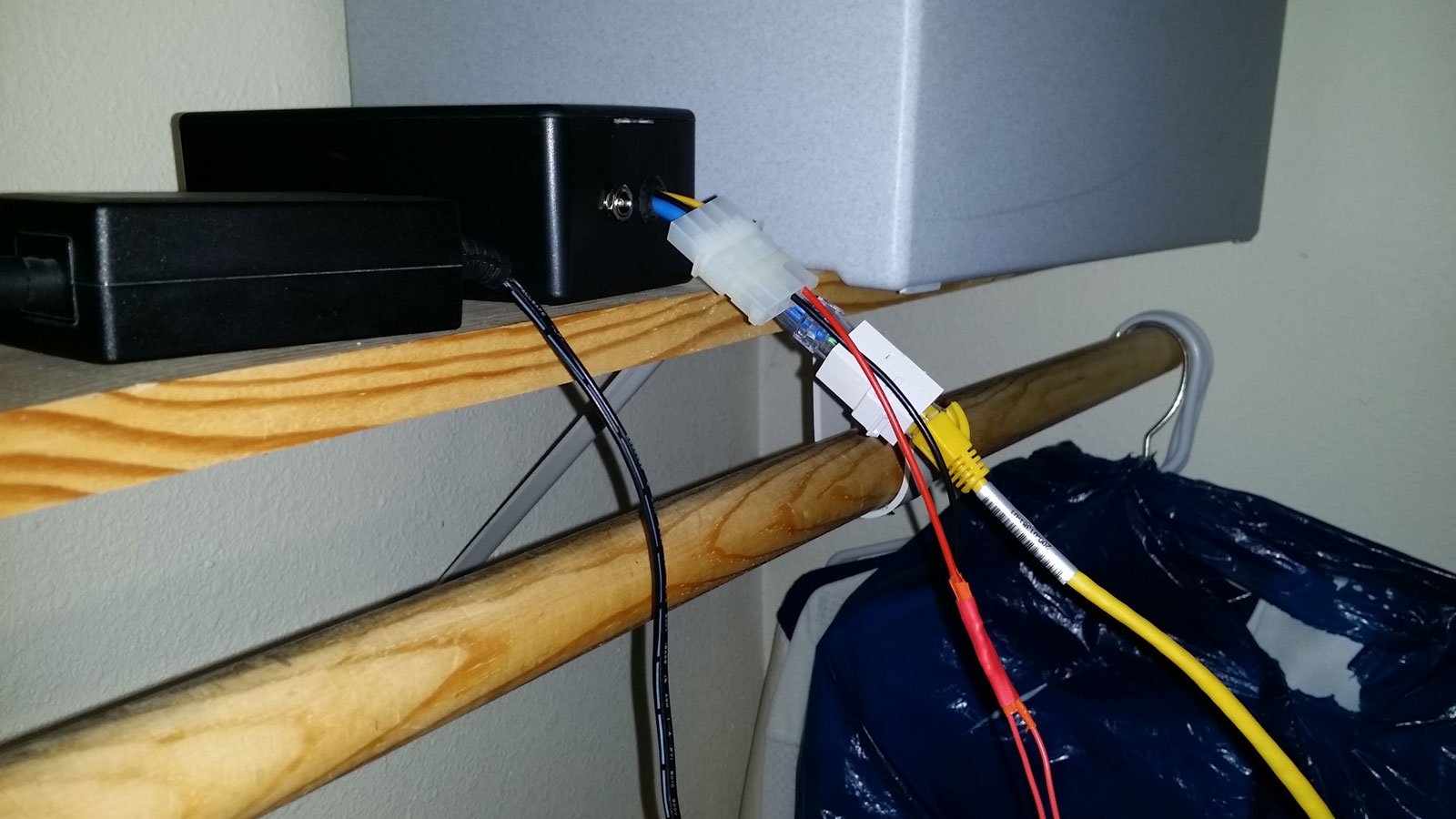
Main Control Box to RFID Reader
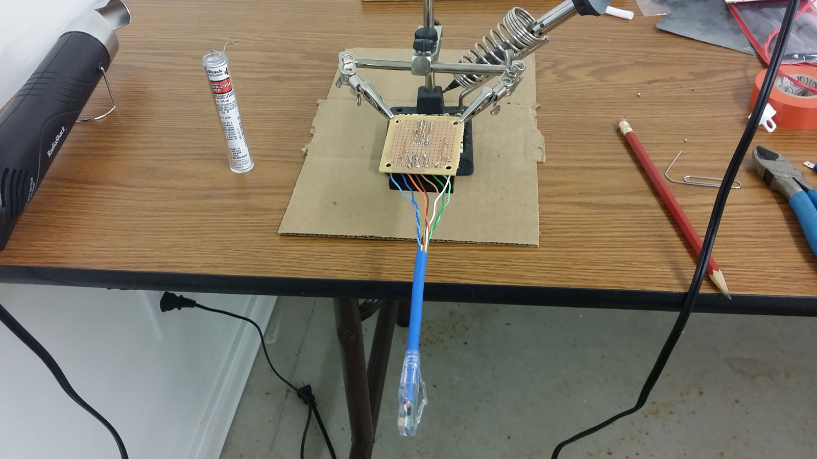
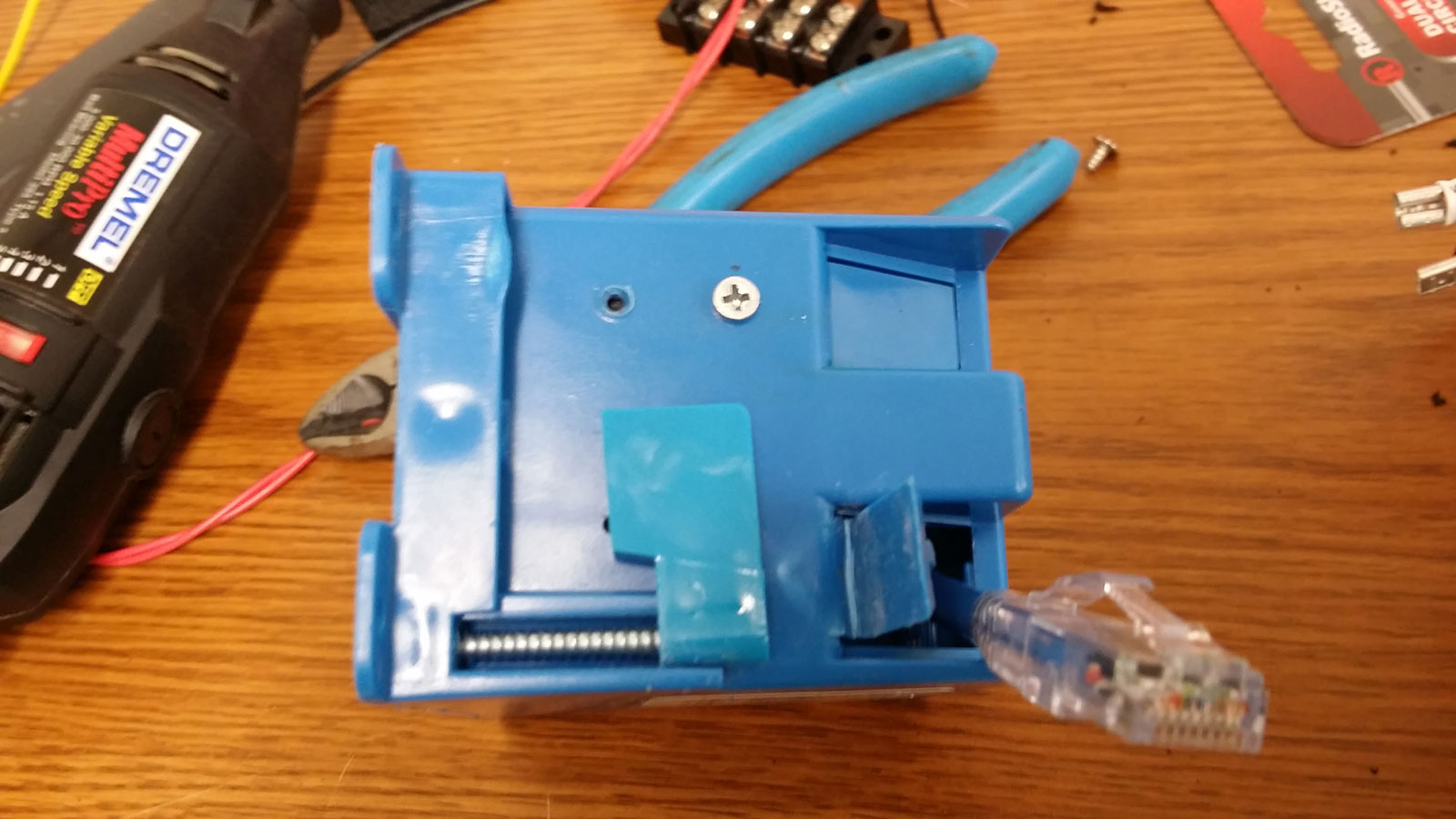
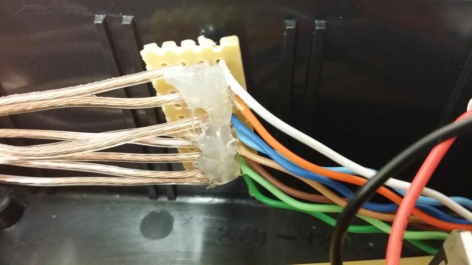
I decided to use category 5 cable terminated with RJ-45 connectors (Ethernet cables) to connected the modules together. Ethernet cables provide a clean interface with 8 different connections at our disposal. Now, the ideal way to do this is to get RJ-45 sockets to mount into the project enclosure for a clean installation. I was scrunched for time and had to settle with an uglier approach, as you will see, using RJ-45 couplers - its the only thing I could get a hold of on short notice.
Here are the pin configurations I used:
- +5V
- GND
- RFID Data
- not used
- not used
- Status LED Red
- Status LED Green
- Status LED Blue
Main Control Box to Door Strike
For the connection between the main control box and the door strike, I used molex connectors connectors I had laying around. Molex connectors slightly annoy me. There are more elegant solutions, but again, it’s what I had laying around. There are only two connections between the door strike and the main control box that connect to the positive and negative leads coming out of the strike.
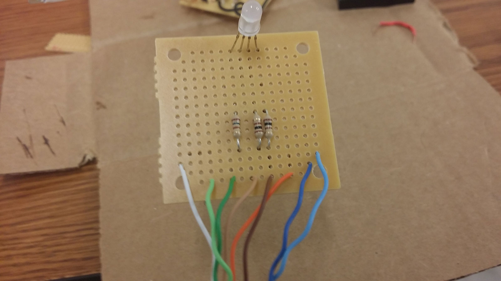
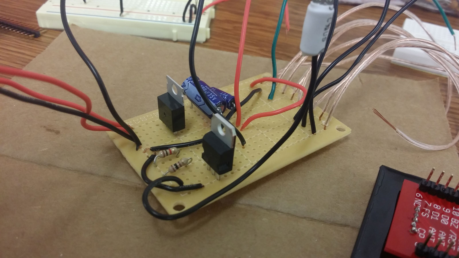
Assembling the RFID Module
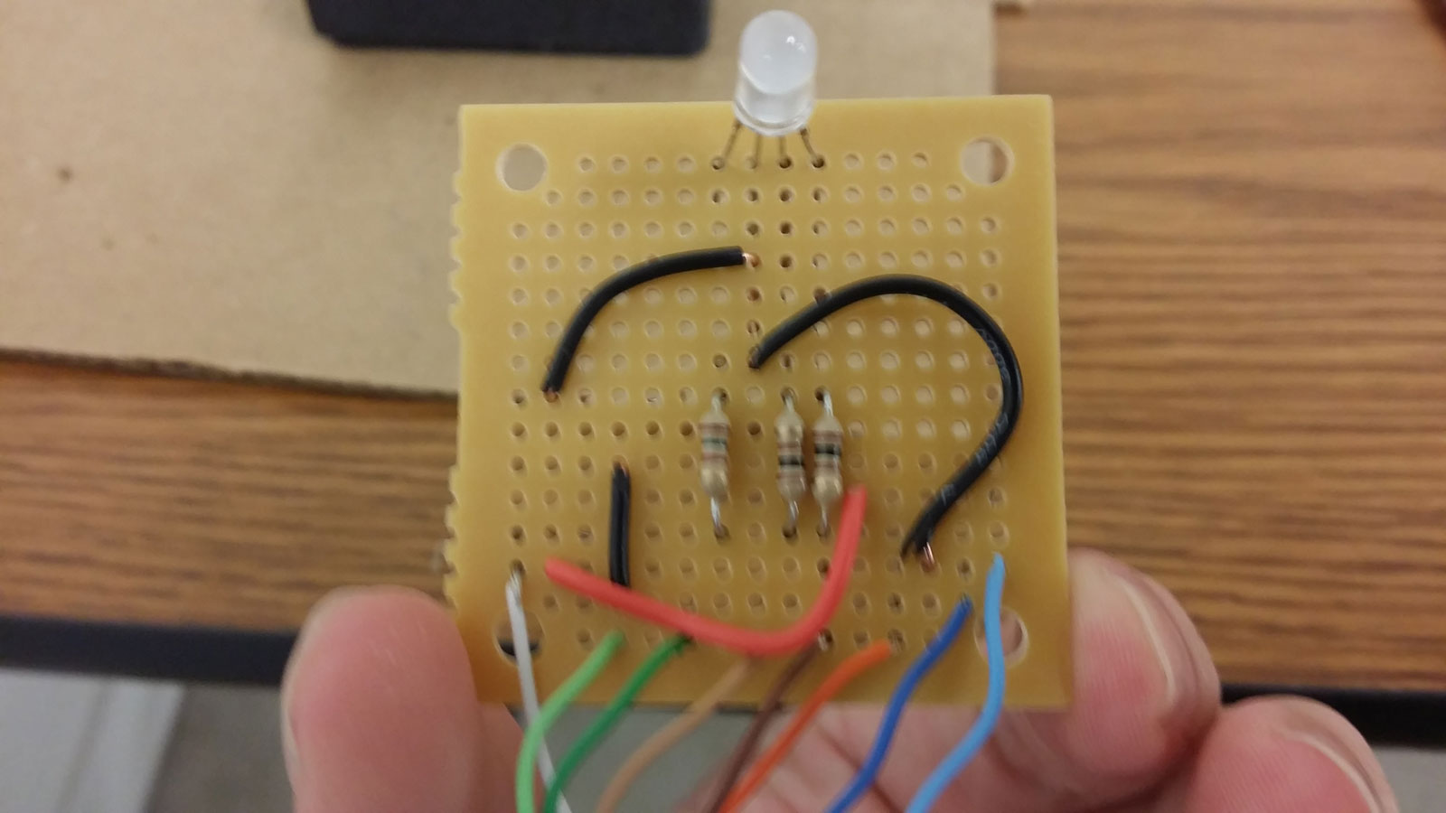
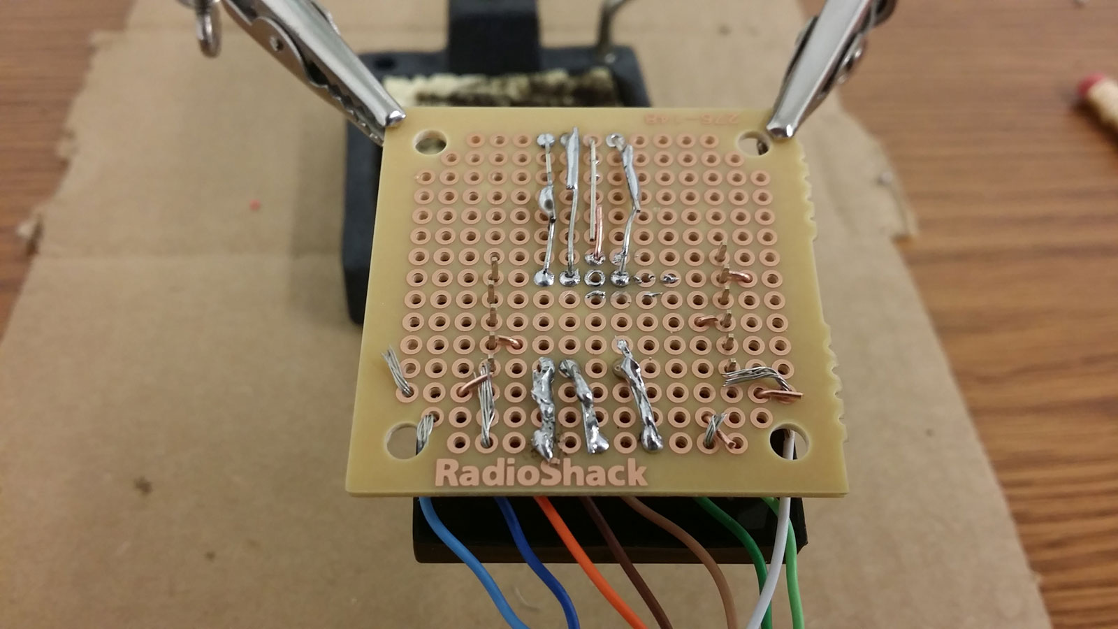
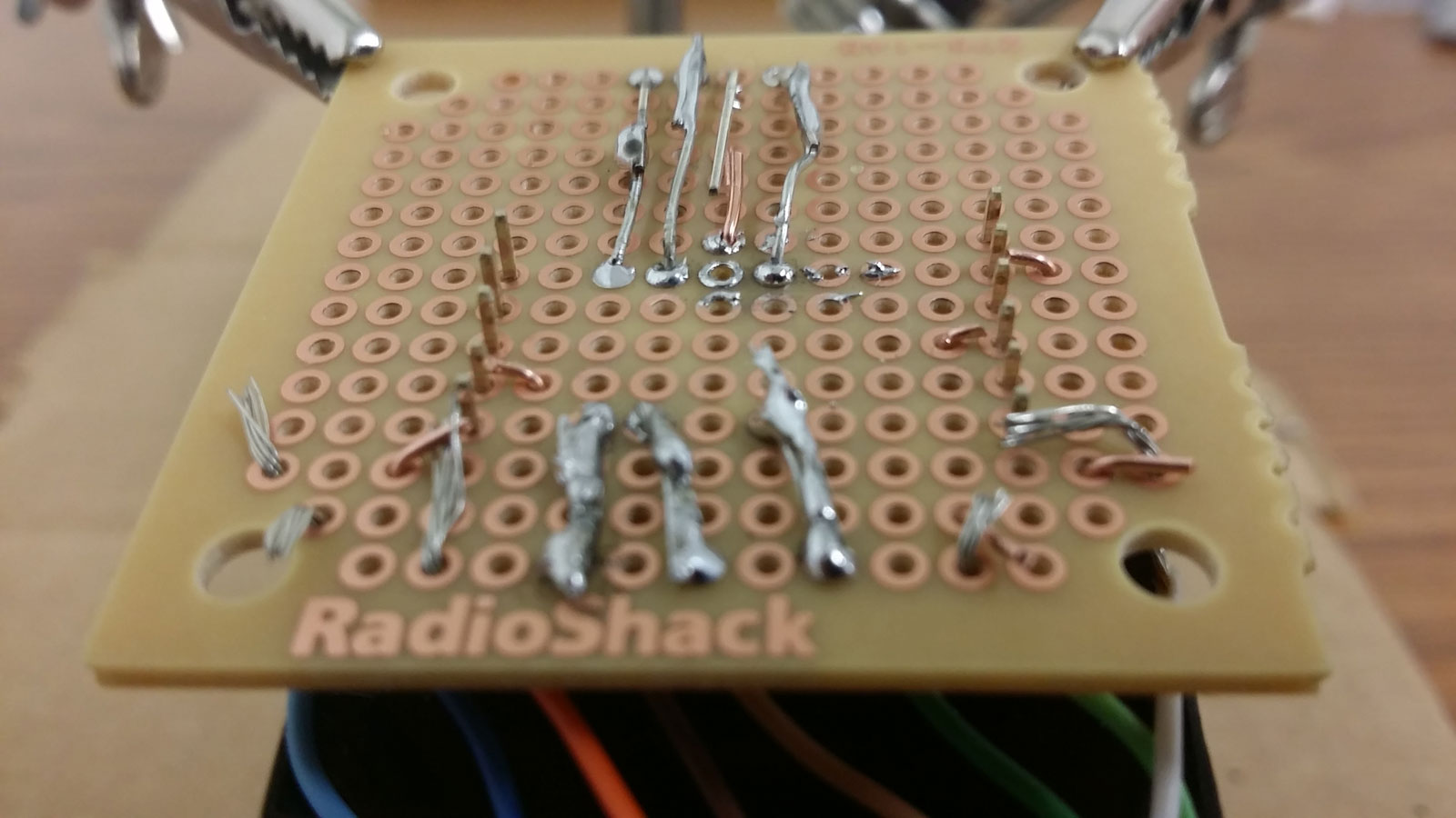
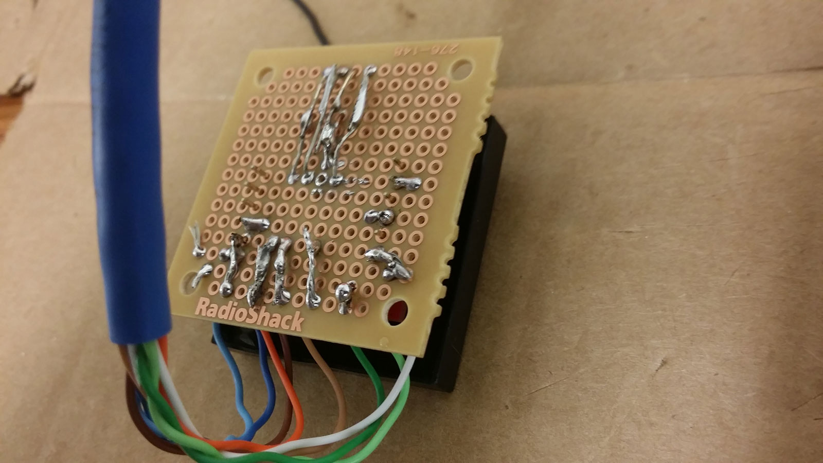
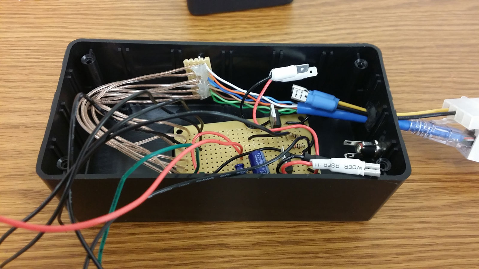
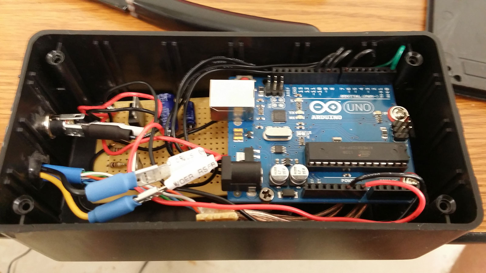
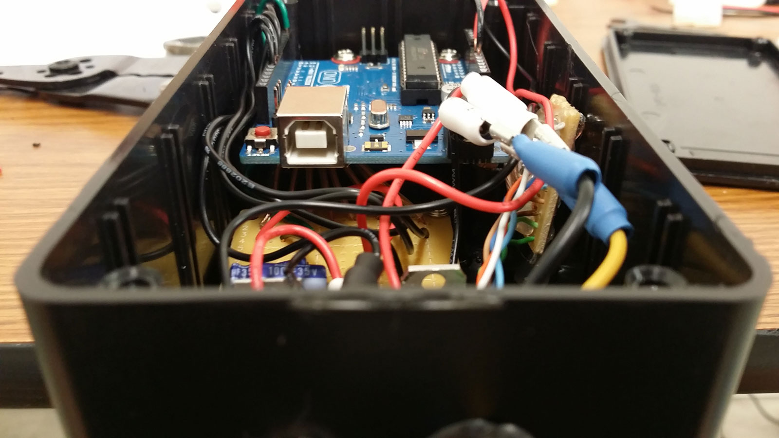
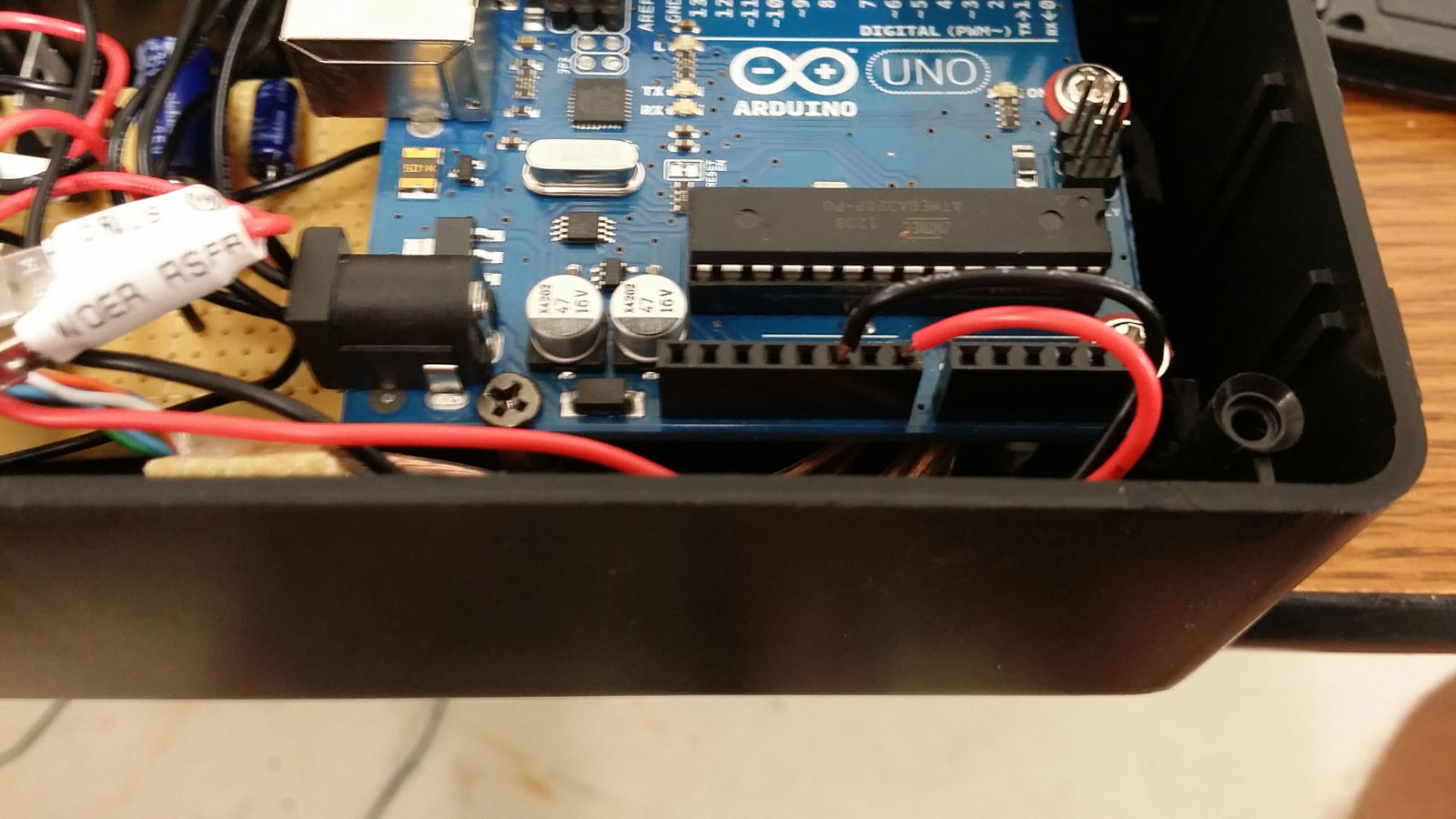
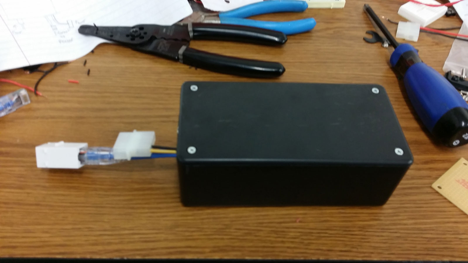
Assembling the Main Control Box
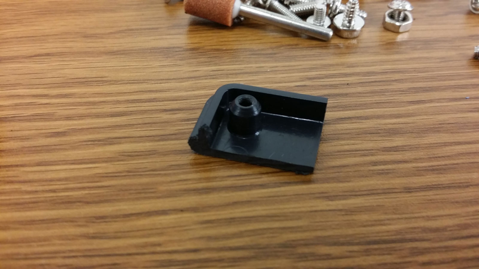
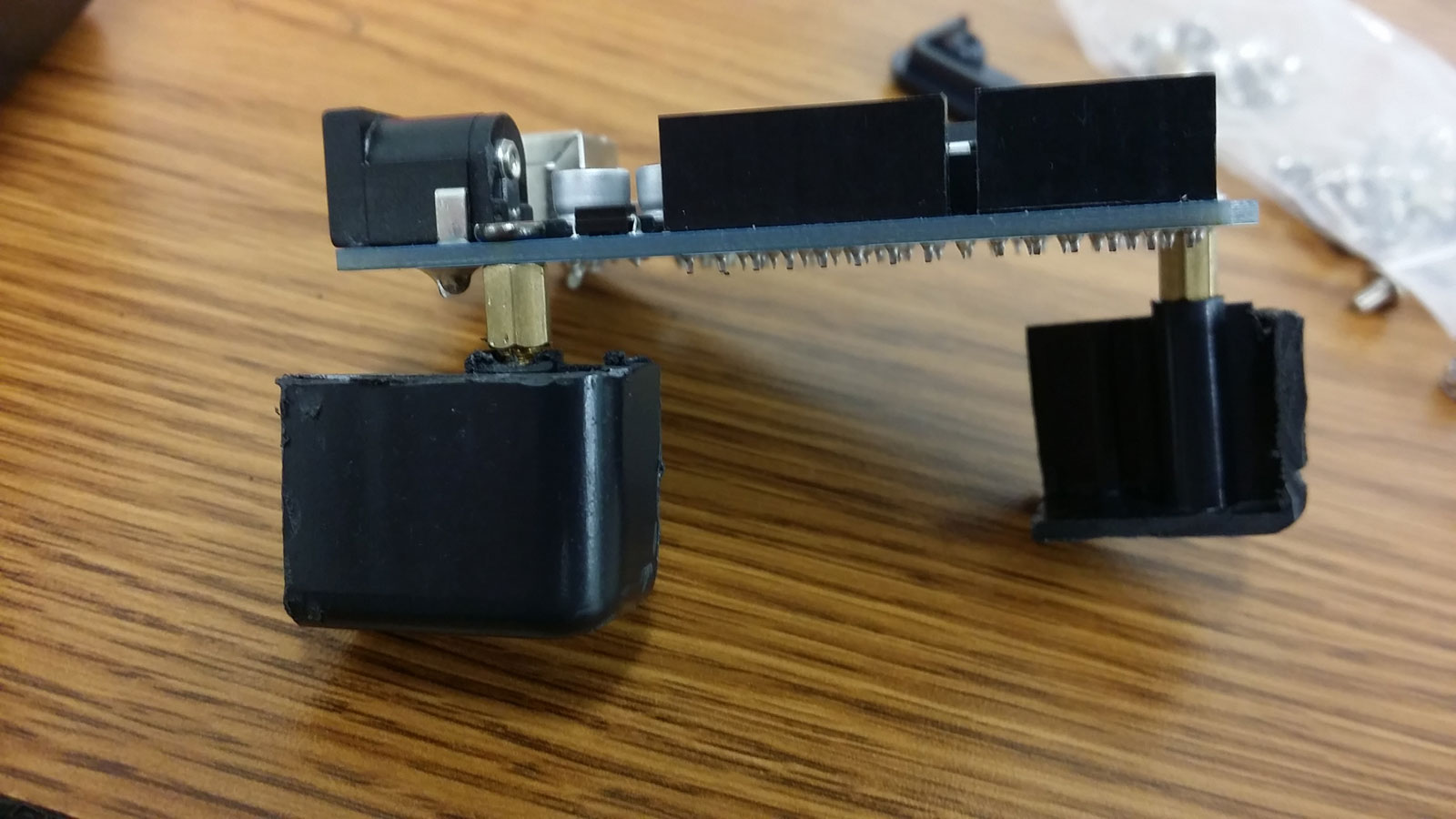
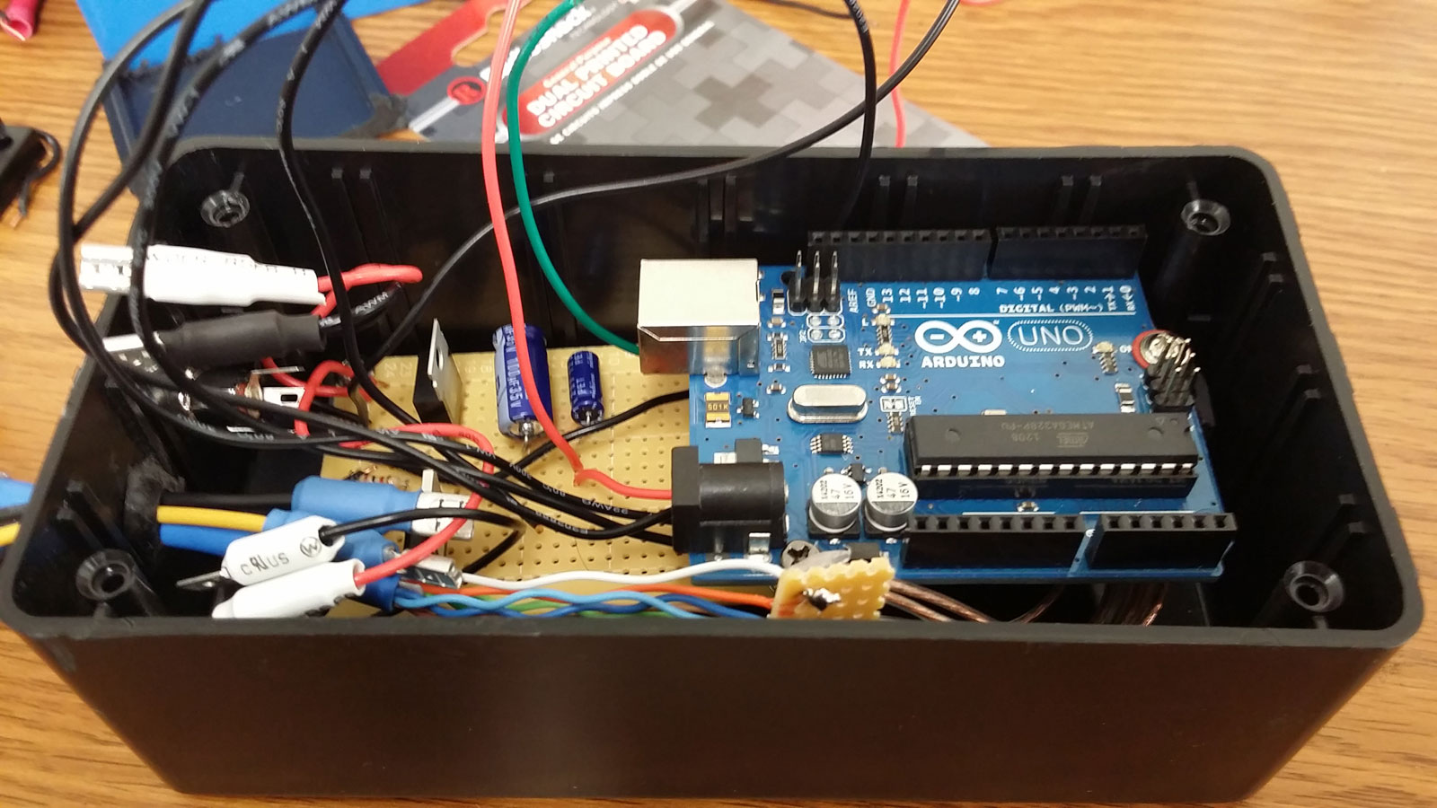
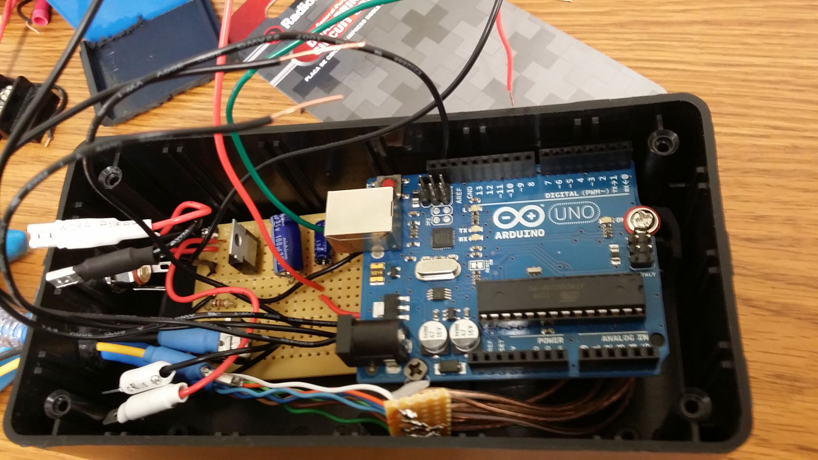
The main control components are housed in a RadioShack project box. I drilled a hole for the power supply connection and a hole to feed out the connections to the RFID module and the door strike (ugly, as noted before, but hey). To fit everything in the box, I created a mount so the Arduino is slightly elevated over the other components. This also provides access to the Arduino’s USB port while the device is still mounted in the box. The Arduino can also be easily removed, which was something I wanted in case I want to use it for something else.
It’s worth noting that you can ditch the Arduino for the final install and get an ATmega238 with Arduino Optiboot. This will reduce the size of your final install and allow you to re-use the Arduino for your next project. Check out this link for details.
Installation
With the components all completed, the only thing left to do was install and test.
Conclusion
This was a fun project and hopefully this write-up can help someone out. This project can be expanded on in an infinite number of ways, so put your imagination to work!
Other References
Here are a couple other articles that were helpful: